
From paper pattern photo to a reviewable DXF draft
This workflow is for pattern makers, studios, and teams preserving or reusing paper patterns. It organizes the input, scale reference, contour extraction, QA, and ET/CAD review instead of promising an automatic production pattern.
A DXF draft still needs review in the ET/CAD version that will receive it.
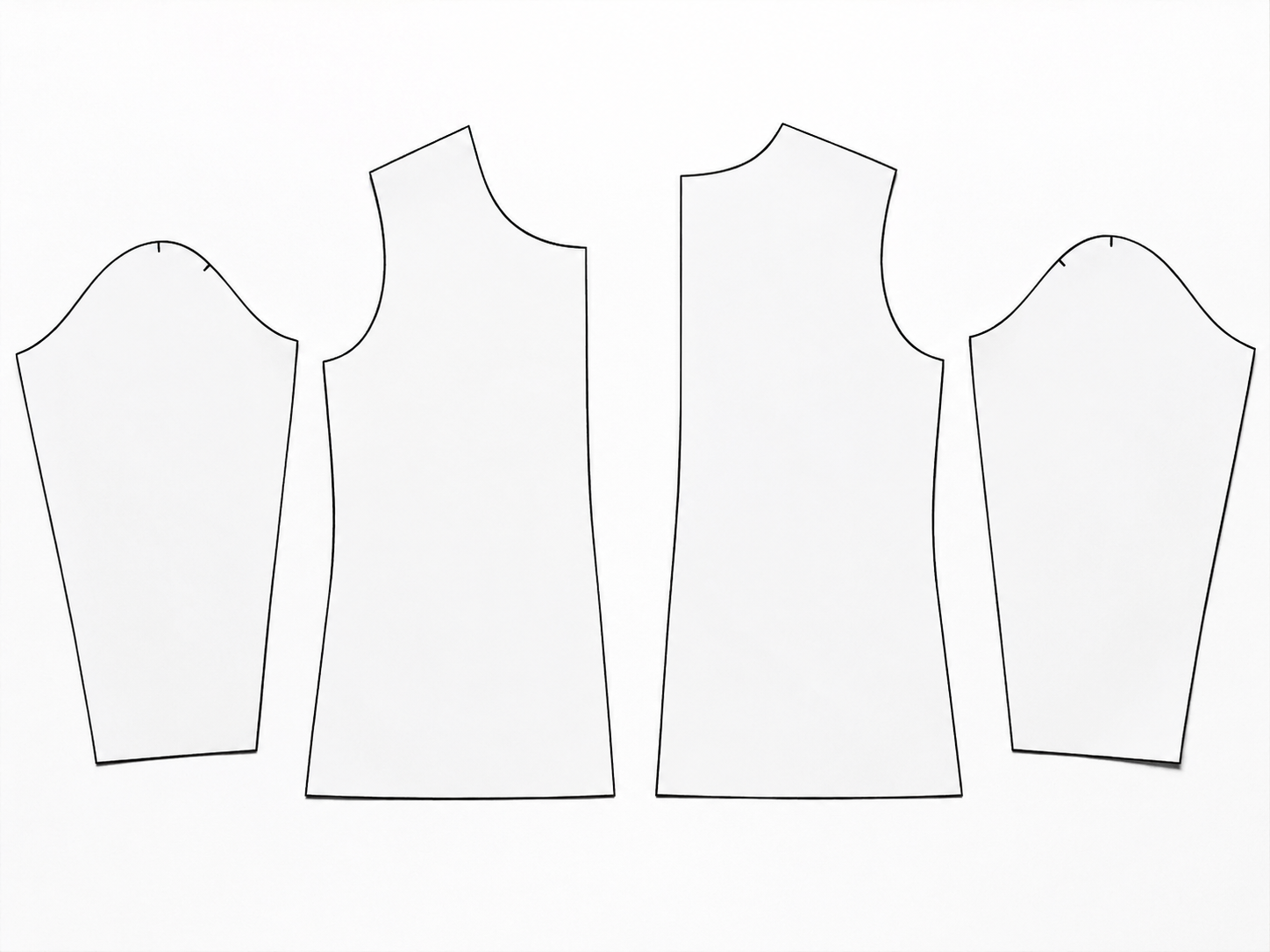
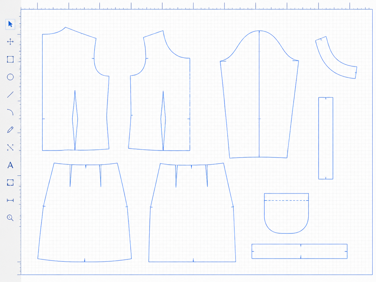
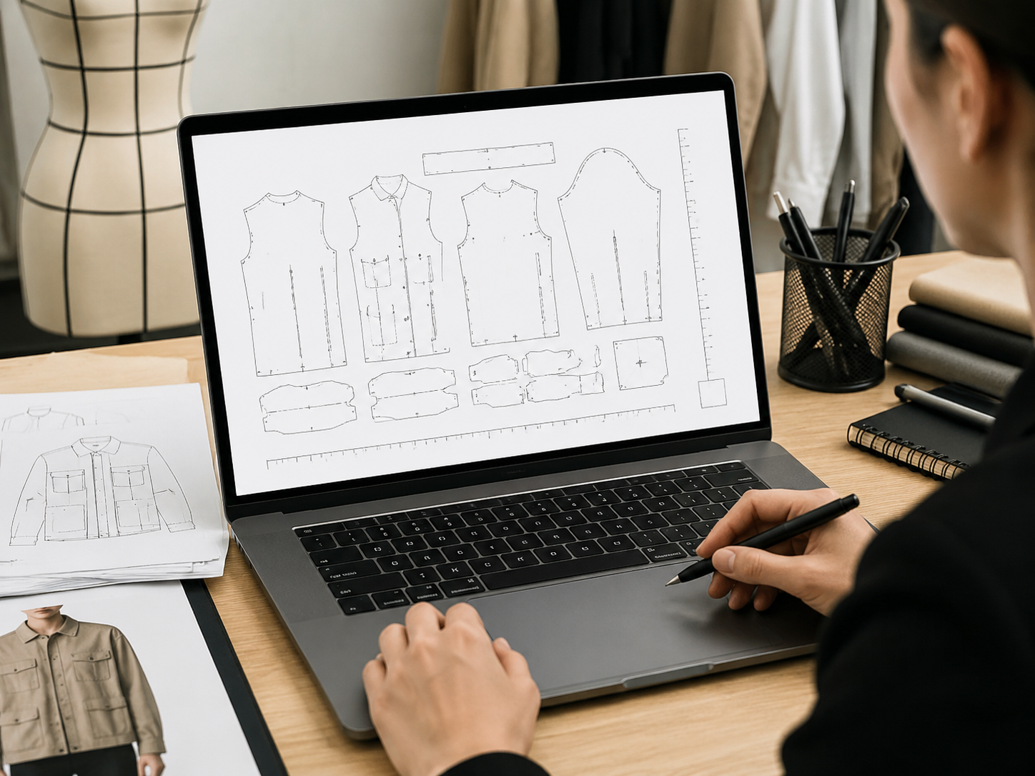
THE TASK
What this scenario is designed to solve
You have a paper pattern, archive image, or scan and need a usable digital starting point for checking, editing, or continuing work in CAD. The output is a traceable draft, not an invented answer for hidden edges or missing pattern information.
THE WORKFLOW
Paper pattern → DXF → ET/CAD review
The conversion is one step in a controlled chain. Each stage has a separate success check so a downloadable file is not mistaken for a finished pattern.
A successful output is verifiable
Judge the result by the checks you can perform, not by whether the export button completed.
- The full input piece is represented without an unmarked invented edge.
- The known physical measurement remains correct after scale calibration.
- Outer contours are closed or clearly flagged for manual repair.
- The expected pieces and important marks can be identified in the DXF.
- The file opens in the actual ET/CAD version used for the next step.
When this workflow should stop
A tool cannot reliably recover information that the source does not show.
- Strong perspective distortion can make measurements and curves unreliable.
- Folds, hands, weights, and shadows can hide the true contour.
- Low contrast or intersecting annotations can make line ownership ambiguous.
- Cropping or missing edges may require returning to the original pattern.
- Seam allowance, grading, and production intent still require professional decisions.
Continue with the right page
JPG to DXF
Start with a clear JPG when the source is a flat image and you need a general DXF draft.
Scan to ET DXF
Use the pattern-focused workflow when scale, QA, and ET/CAD review are central to the task.
How to digitize a sewing pattern
Prepare the photo or scan and learn which failure modes to check before conversion.
Pattern digitization workflow
Review the service-style workflow and the boundary between a draft and a production pattern.
FAQ
Questions about this workflow
Ready to review one representative pattern?
Start with one source image, one known measurement, and the ET/CAD version you will use to inspect the result.